Stripline to Microstrip Line Transition
A vertical transition from a stripline to a microstrip line through a shared substrate, connected by a conducting via.
Introduction
This tutorial covers:
Setup of a stripline port and a microstrip line port on the same substrate stack
A plated via connecting the stripline to the microstrip pad through a split ground plane
Calculate the S-Parameter (S11, S21) of the transition
Python Script
Get the latest version from git.
import os, tempfile
import numpy as np
import matplotlib.pyplot as plt

from CSXCAD  import ContinuousStructure
from openEMS import openEMS
from openEMS.physical_constants import *
Setup the simulation
Sim_Path = os.path.join(tempfile.gettempdir(), 'StripLine2MSL')
post_proc_only = False

unit = 1e-6  # drawing unit in um

line_length              = 15000
substrate_width          = 10000
air_spacer               = 4000

msl_width                = 500
msl_substrate_thickness  = 254

strip_width              = 500
strip_substrate_thickness = 512

connect_via_rad  = 500/2
connect_via_gap  = 1250/2

substrate_epr   = 3.66
substrate_kappa = 1e-3 * 2*np.pi*2.45e9 * EPS0 * substrate_epr

f_max       = 10e9
resolution  = 250
edge_res    = 25
feed_shift  = 2500
meas_shift  = 5000
Setup FDTD parameters & excitation
FDTD = openEMS(EndCriteria=1e-4)
FDTD.SetGaussExcite(f_max/2, f_max/2)
FDTD.SetBoundaryCond(['PML_8', 'PML_8', 'MUR', 'MUR', 'PEC', 'MUR'])
Setup CSXCAD geometry & mesh
CSX = ContinuousStructure()
FDTD.SetCSX(CSX)
mesh = CSX.GetGrid()
mesh.SetDeltaUnit(unit)

edge_mesh = np.array([-1/3, 2/3]) * edge_res

mesh.AddLine('x', [-connect_via_gap, 0, connect_via_gap])
mesh.SmoothMeshLines('x', 2*edge_res, ratio=1.5)
mesh.AddLine('x', [-line_length, line_length])
mesh.SmoothMeshLines('x', resolution, ratio=1.5)

mesh.AddLine('y', [0])
mesh.AddLine('y', msl_width/2 + edge_mesh)
mesh.AddLine('y', substrate_width/2)
mesh.SmoothMeshLines('y', resolution/4, ratio=1.5)
y_pos = mesh.GetLines('y')
mesh.AddLine('y', -y_pos[y_pos > 0])

x_linex = mesh.GetLines('x', do_sort=True)
y_lines = mesh.GetLines('y', do_sort=True)

z_levels = np.concatenate([
    np.linspace(-strip_substrate_thickness, 0, 5),
    np.linspace(0, strip_substrate_thickness, 5),
    np.linspace(strip_substrate_thickness,
                strip_substrate_thickness + msl_substrate_thickness, 5),
    [2*strip_substrate_thickness + air_spacer],
])
mesh.AddLine('z', z_levels)
mesh.SmoothMeshLines('z', resolution)
Substrate (lossy)
substrate = CSX.AddMaterial('RO4350B', epsilon=substrate_epr, kappa=substrate_kappa)
start = [x_linex[0], -substrate_width/2, -strip_substrate_thickness]
stop  = [x_linex[-1], substrate_width/2,  strip_substrate_thickness + msl_substrate_thickness]
substrate.AddBox(start, stop)
Metal properties
gnd   = CSX.AddMetal('gnd')
metal = CSX.AddMetal('metal')
Stripline port (port 1) with strip metal
portstart = [-line_length, -strip_width/2, 0]
portstop  = [0,             strip_width/2, 0]
port1 = FDTD.AddStripLinePort(1, metal, portstart, portstop, 'x', 'z',
                              strip_substrate_thickness,
                              excite=1, priority=100,
                              FeedShift=feed_shift, MeasPlaneShift=meas_shift)
MSL port (port 2) on top surface
portstart = [line_length,  -strip_width/2, strip_substrate_thickness + msl_substrate_thickness]
portstop  = [0,             strip_width/2, strip_substrate_thickness]
port2 = FDTD.AddMSLPort(2, metal, portstart, portstop, 'x', 'z',
                        priority=100, MeasPlaneShift=meas_shift)

ports = [port1, port2]
Transition via connecting strip to MSL pad
start = [0, 0, 0]
stop  = [0, 0, strip_substrate_thickness + msl_substrate_thickness]
metal.AddCylinder(start, stop, connect_via_rad, priority=100)
Ground plane between strip and MSL with hole for via
# Ground plane with circular cutout for the via, split into left and right halves.
x0 = x_linex[0]
x1 = x_linex[-1]
y0 = y_lines[0]
y1 = y_lines[-1]

theta_l = np.linspace(-np.pi, 0, 11)
pts_x = np.concatenate([[x0, 0], connect_via_gap * np.sin(theta_l), [0, x0]])
pts_y = np.concatenate([[y0, y0], connect_via_gap * np.cos(theta_l), [y1, y1]])
gnd.AddPolygon([pts_x, pts_y], norm_dir=2, elevation=strip_substrate_thickness, priority=100)

theta_r = np.linspace(0, np.pi, 11)
pts_x = np.concatenate([[0, x1, x1, 0], connect_via_gap * np.sin(theta_r)])
pts_y = np.concatenate([[y0, y0, y1, y1], connect_via_gap * np.cos(theta_r)])
gnd.AddPolygon([pts_x, pts_y], norm_dir=2, elevation=strip_substrate_thickness, priority=100)

if 1:  # debugging only
    CSX_file = os.path.join(Sim_Path, 'simp_patch.xml')
    if not os.path.exists(Sim_Path):
        os.mkdir(Sim_Path)
    CSX.Write2XML(CSX_file)
    from CSXCAD import AppCSXCAD_BIN
    os.system(AppCSXCAD_BIN + ' "{}"'.format(CSX_file))
Run the simulation
if not post_proc_only:
    FDTD.Run(Sim_Path, cleanup=True, debug_PEC=True)
Post-processing
f = np.linspace(0, f_max, 1601)
for port in ports:
    port.CalcPort(Sim_Path, f, ref_impedance=50)

s11 = ports[0].uf_ref / ports[0].uf_inc
s21 = ports[1].uf_ref / ports[0].uf_inc

fig, axis = plt.subplots(num='S-Parameters', tight_layout=True)
axis.plot(f/1e9, 20*np.log10(abs(s11)), 'k-',  linewidth=2, label='$S_{11}$')
axis.plot(f/1e9, 20*np.log10(abs(s21)), 'r--', linewidth=2, label='$S_{21}$')
axis.grid()
axis.set_xmargin(0)
axis.set_ylim([-40, 2])
axis.set_xlabel('Frequency (GHz) $\\rightarrow$')
axis.set_ylabel('S-Parameter (dB)')
axis.legend()

plt.show()
Images
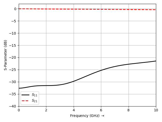
S-Parameter (S11, S21) of the stripline to microstrip transition